ANTENNAS
An antenna is a transducer.
Antennas convert electrical energy (RF) from a transmitter into electromagnetic
waves that propagate away from the antenna at the speed of light.
A useful analogy is a speaker or microphone, both transducers.
A signal (the music waveforms) from an amplifier is connected to the speaker,
thus converting electrical energy to sound energy.
A microphone does the opposite, converting sound pressure to electricity.
Most antennas work in both directions, however, there are some that are for receiving only.
Antennas come in 2 basic types, resonant and non-resonant.
The resonant ones are tuned to a specific fairly narrow frequency band.
Some antennas can be made to resonate on multiple bands using coils.
A good example is the Nagoya 3 band VHF UHF on top of my car, see pics below.
The taller one, Wilson 1000, is resonant on the 10 Meter band.
Most broadband antennas by their nature are non-resonant.
The pizza pan antennas described below are good examples.
A simple piece of wire can be an antenna at some frequency determined by it's length.
There are hundreds of more complex antenna designs in use today.
Below are pictures of some of my antennas.
Then we'll discuss some car radio antennas.
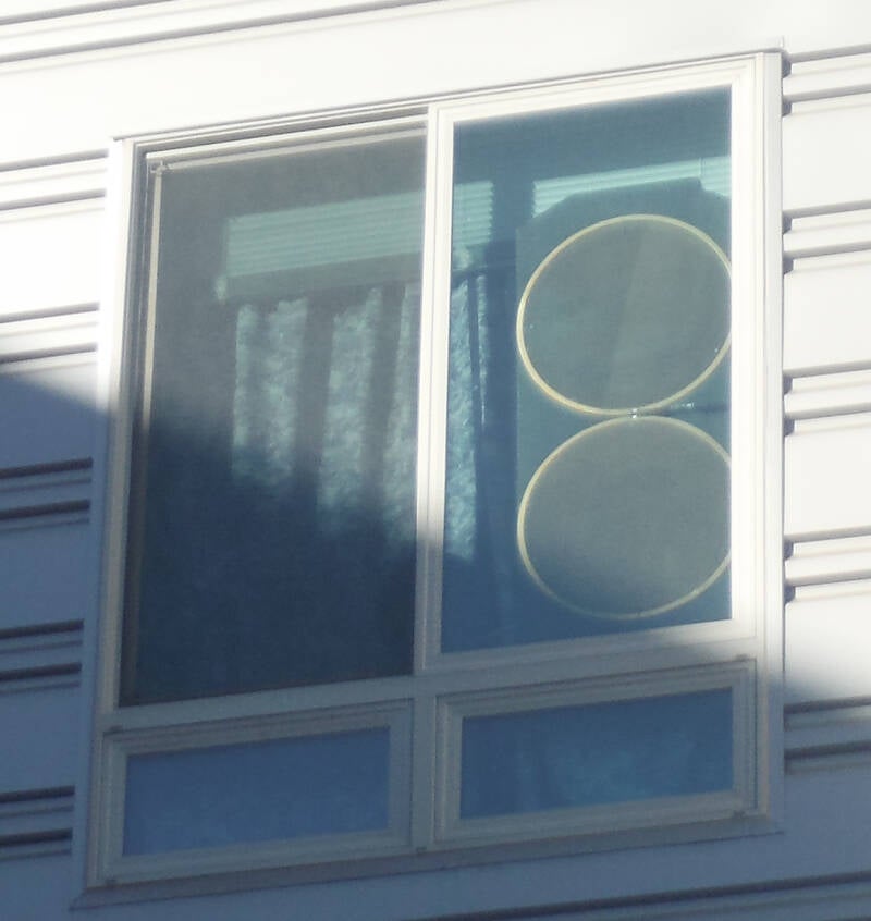
This antenna in my 3rd floor south facing window is a pizza pan antenna.
It was made using 18" grid pizza pans.
They were the largest they had at a restaurant supply store.
It is Vertically polarized, non-resonant and used for
The VHF and UHF HAM bands, 144, 220 and 440 MHZ.
It works well up to around 1 GHz.
These broadband antennas can transmit as well as receive.
The feedpoint impedance is 300 Ohms,
I use a RF transformer to change it to 50 Ohms so it
matches the transceiver it's connected to.
It's barely visible to the right between the pans.
You can see the 2 screws at the feedpoint.
See the chart on the HAM radio page.
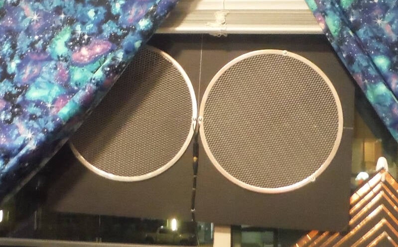
This horizontal polarized pizza pan antenna is in my living room window,
used for off the air (OTA) TV.
Broadband and non resonant.
It's made using 13" grid pizza pans.
The transformer is in the middle.
The spacing at the feedpoint needs to be very close,
as it determines the highest frequency of use.
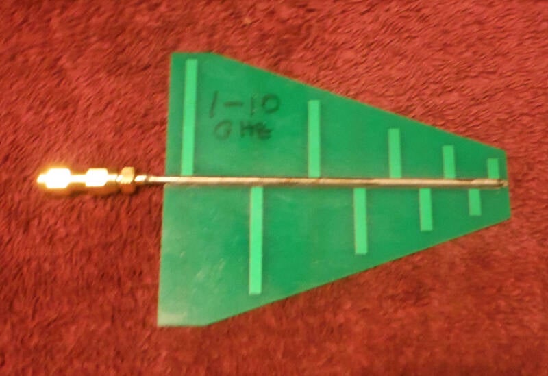
This little (4") antenna works from 1 GHz to 10 GHz and is highly directional.
It is called a Log-periodic antenna.
This design blurs the line between resonant and non-resonant.
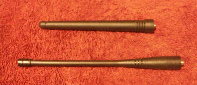
These antennas came with my Baofeng F8HP PRO 3 band handheld transceiver.
The top, shorter one is mainly for the 220 MHz HAM band.
It also works for several higher frequency bands that are not HAM bands.
The lower, longer one is for 144 and 440 MHz HAM bands.
Antennas this short (for that frequency) are not very efficient,
as they waste much of the RF energy sent to them from the transmitter.
Cutting into them would reveal several coils of wire that
fool the radio (transmitter) into thinking they are a normal length resonant antenna.
The coils inside this type of antenna are made to resonate in 1 or more HAM bands.
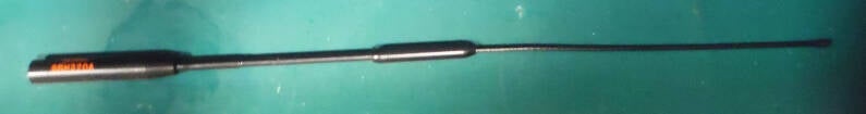
This is a Diamond SRH320A antenna for Handheld HAM radios.
It is similar to the shorter ones above, but is longer (14"), naturally making it more efficient.
There are 2 coils, bottom and middle.
Works well on all 3 VHF/UHF HAM bands, so you don't have to change antennas to change bands.
It is resonant on those 3 bands.
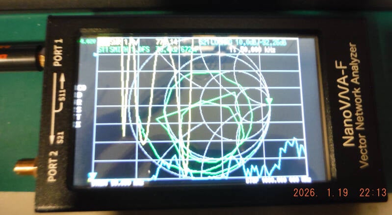
This NanoVNA, among it's other RF functions, can be used to test antennas.
The yellow line shows the 3 resonant frequencies of the SRH320A,
144, 220 and 440 MHz.
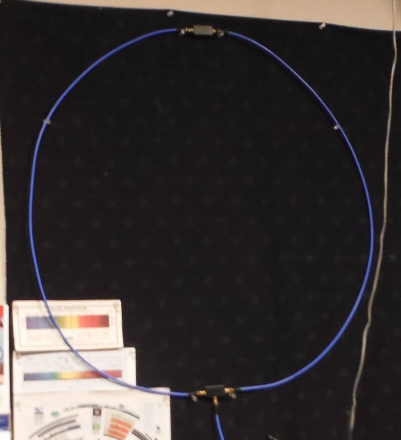
This antenna is called a YOULOOP.
It is up on the wall in my radio room (often called the "Ham Shack").
It works as a broadband (non resonant) receive antenna from about 2 MHz up thru VHF.
It can be a low power transmit antenna, but it's not very efficient.
It picks up both electric and magnetic parts of the signal.
It is connected to the SDR Play RSP2 interface.
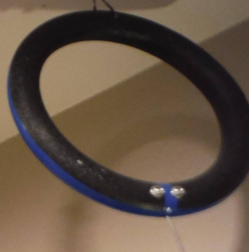
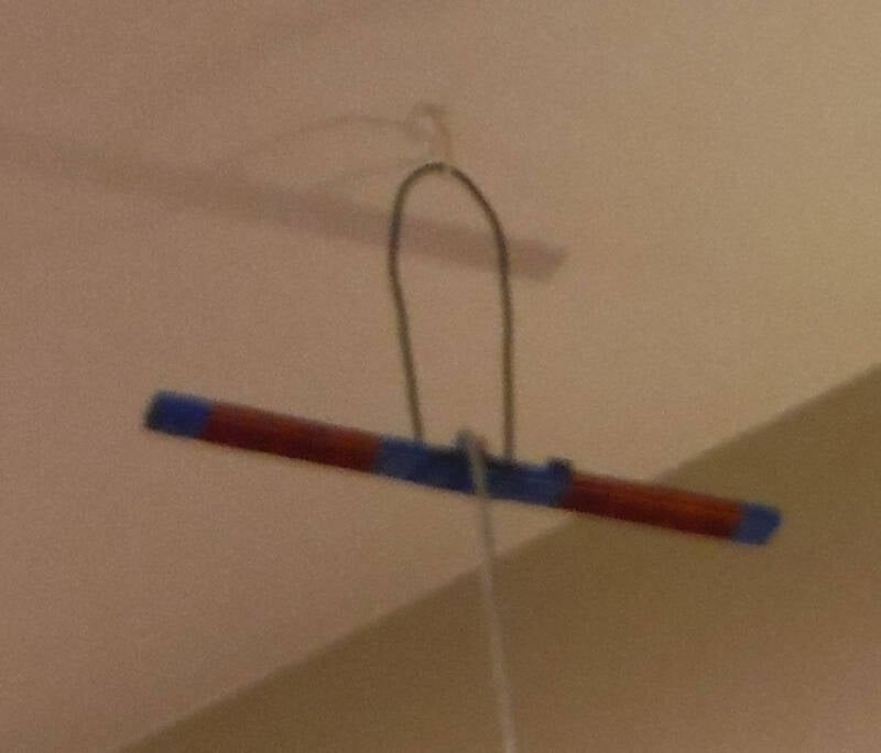
This is a homebrew loop antenna, hung from the ceiling, used mainly for the AM Broadcast band.
It has 9 turns of wire around the form, wire is under the blue tape.
It does work a bit above and below the AM -BCB. Non resonant and not useful for transmitting.
This is a large ferrite magnetic loopstick antenna, also hung from the ceiling.
It has hundreds of turns of fine wire around a large ferrite rod.
Very useful from around 10 kHz to 400 kHz, called VLF for Very Low Frequency.
This type of non-resonant antenna picks up the magnetic part of the signal.
The electric part of the signal is ignored.
Both this and the circle one above are connected thru a switch to the
High Impedance input of the SDR Play RSP-2 interface.
The RSP-2 interface is sadly no longer available from SDR Play.
So glad I bought one a few years ago.
Their more recent products lack the Hi-Z input for magnetic antennas like the 2 above.
They aren't resonant, not broadband and won't work if connected to a 50 Ohm input.
Also, not for transmitting.
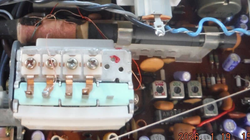
Inside this AM-FM Stereo receiver lurks this ferrite loopstick antenna that picks up the AM-BCB stations.
It's the long grey thing with a coil to the left.
The white thing is the variable tuning capacitor that connects to the coil.
It is resonant at a frequency determined by the variable tuning capacitor.
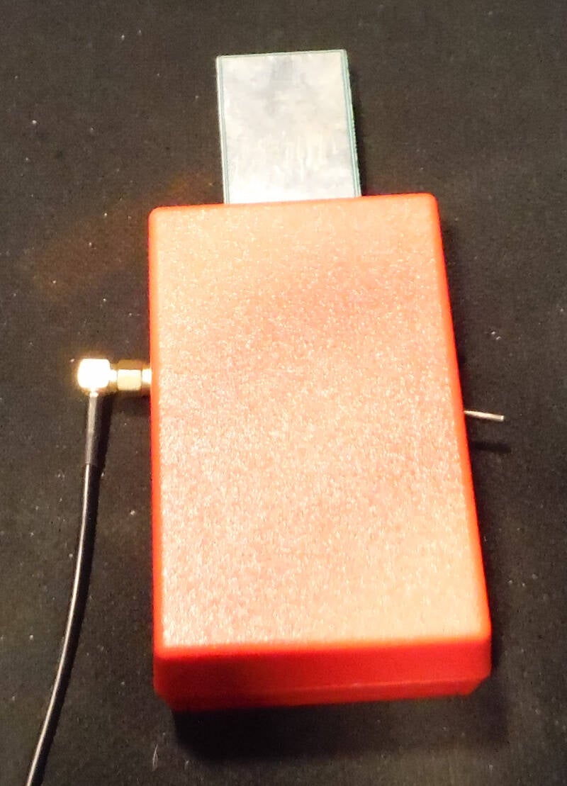
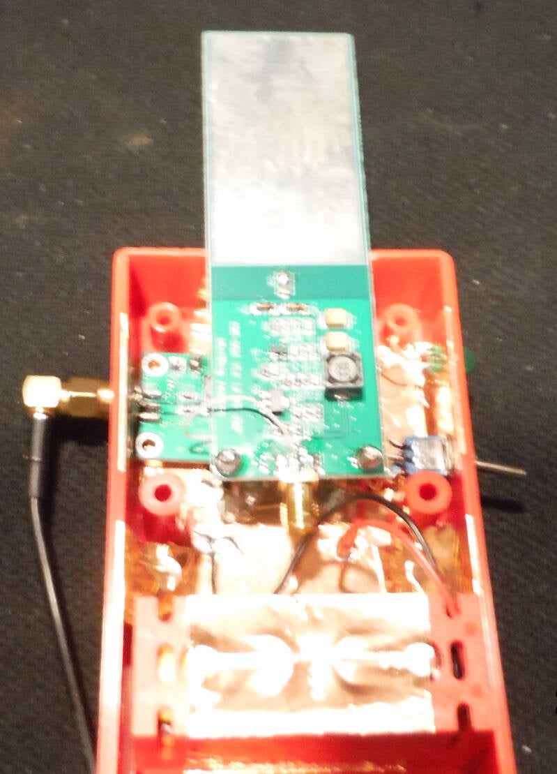
The opposite of magnetic antennas, This weird antenna is called a "voltage probe."
It pics up just the electric part of the wave, the magnetic part is ignored.
The amplifier has a very high input impedance and works from about 100 kHz to 30 MHz.
Output is a standard 50 Ohms.
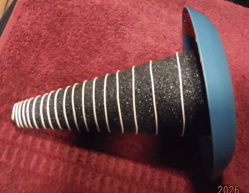
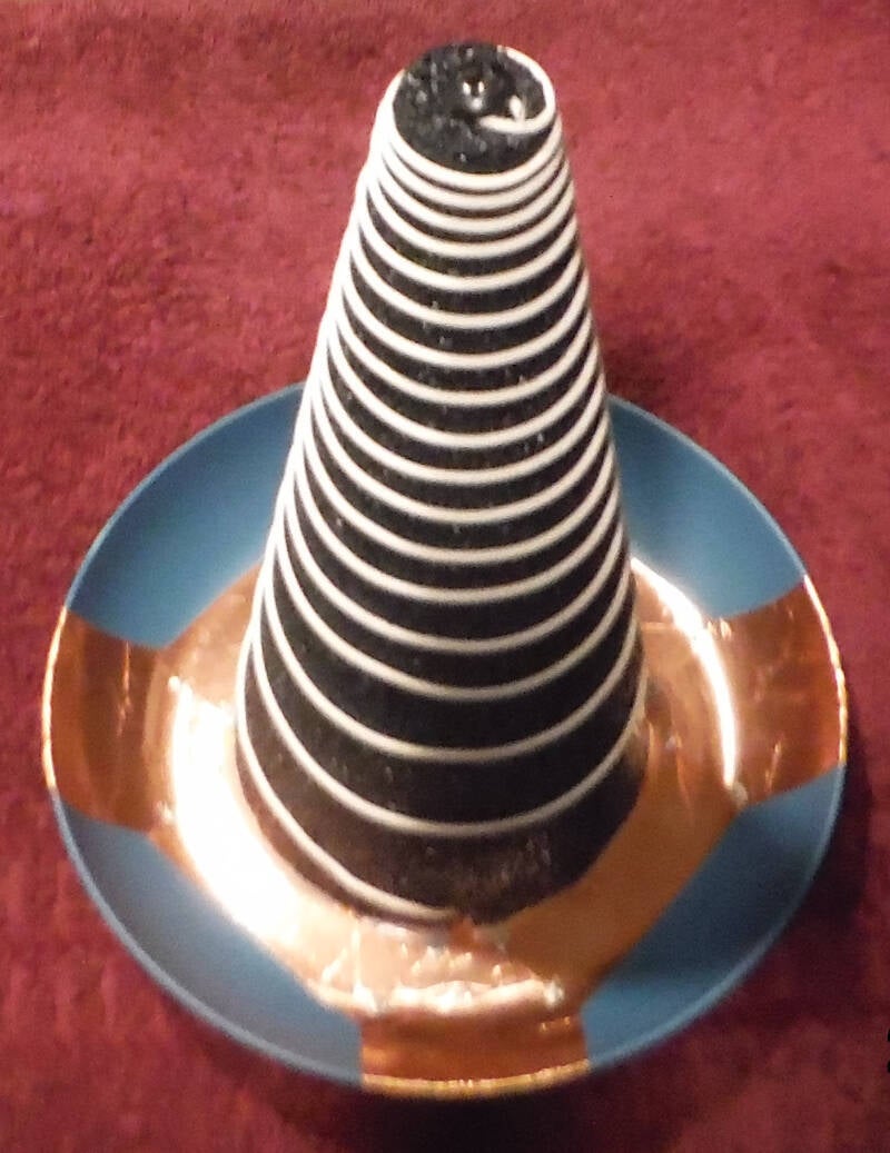
This is a very experimental non resonant antenna.
It is a cross between log-periodic and helical antennas.
It combines a wide frequency range and is highly directional.
It can be used for transmitting as well as receive.
It is circular polarization and will pick up both vertical and horizontal signals.
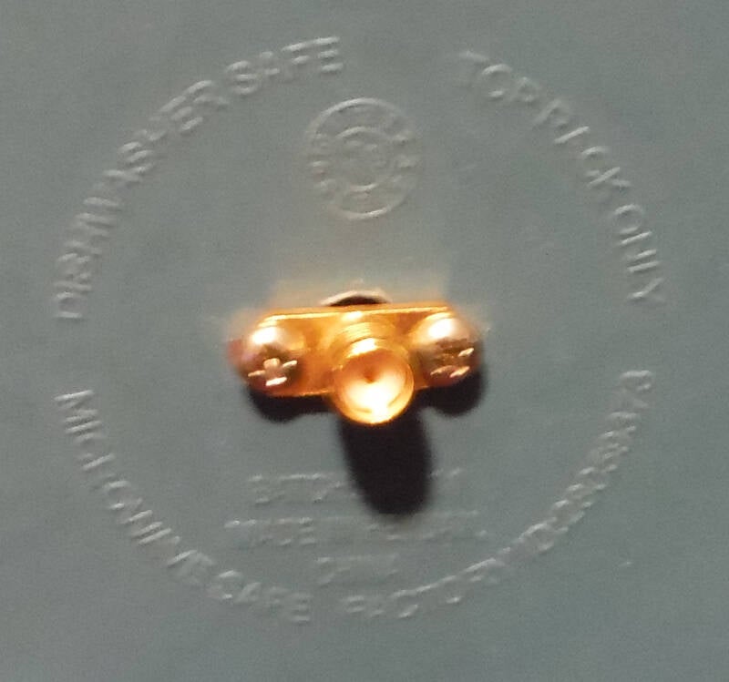
The gold connector is called SMA. I got the form at Walmart.
The backing is a plastic plate with copper foil ground plane.
I'm amazed at how well this baby works.
Testing found a frequency range from about 100 MHz (FM-BCB) up to 2 GHz.
Next is a section about the
Evolution of Car Radio Antennas

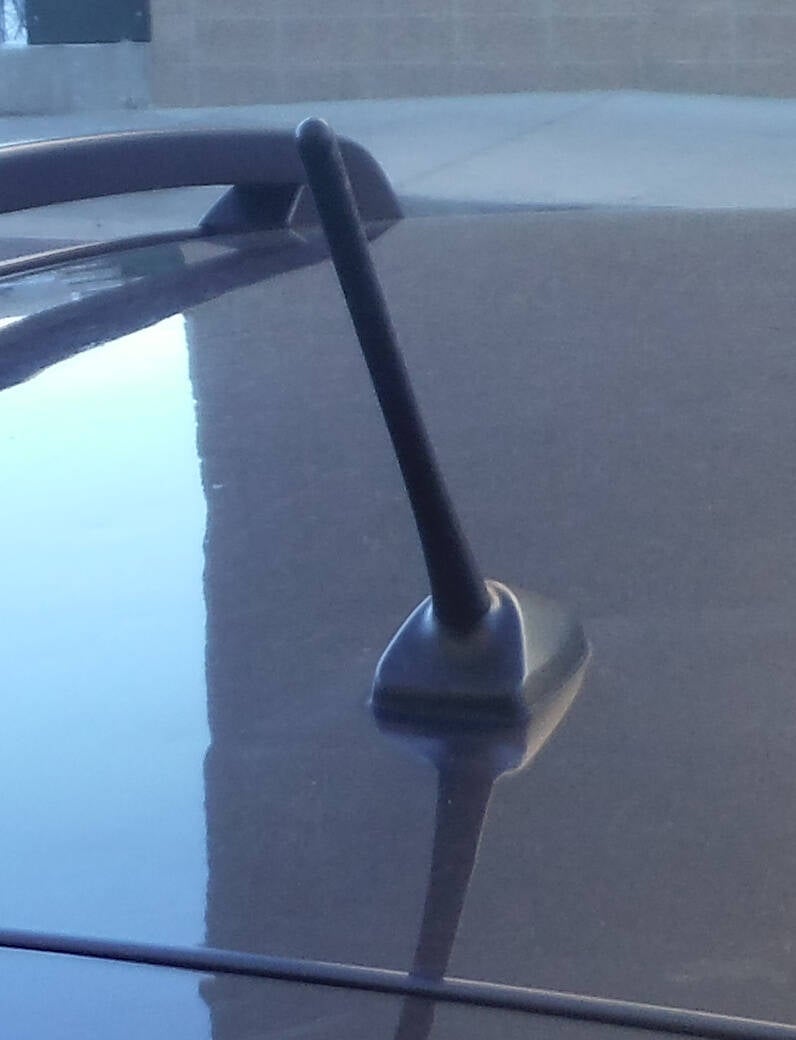
This is a typical 'old school" car radio antenna.
It is about 30-32" length, resonant for the FM-BCB around 100 MHz.
It picks up both the electric and magnetic parts of the signal on the FM-BCB.
It is a tiny fraction of the size of E-M waves in the AM-BCB around 1 MHz.
It picks up the electric part of the wave connected to the car's radio using
special low capacitance high impedance coax to the radio.
This type of car antenna has been in use for many decades.
The car's metal body serves as the ground for these antennas.
Over the last few decades,
car companies have decided to make smaller and smaller
antennas that aren't very efficient on the AM-BCB.
I suppose they consider the above type of antenna not pretty enough.
The pics below illustrate just that.
More recently, the car companies want to stop equipping
their vehicles with radios that receive the AM-BCB.
If they do this, you'll only have an FM radio in new cars.
Let's hope that doesn't happen.
There is a bill in Congress called an "AM Radio in every car act."
Electric cars generate so much RF noise that AM radio reception is not good.
The noise could be improved with old school longer antennas, but car makers won't do that.
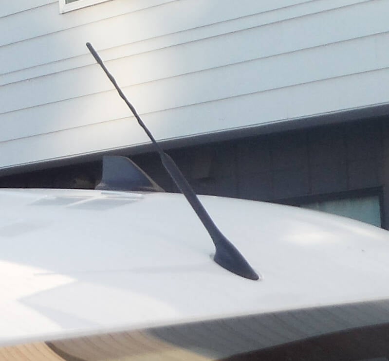
This is a newer type of car antenna used on millions of 10-20 year old cars.
Being shorter, it's inefficient compared to the older car's antennas.
They make up for that by using an amplifier between the antenna and radio.
Similar to the one above, this one is newer, shorter and less efficient.
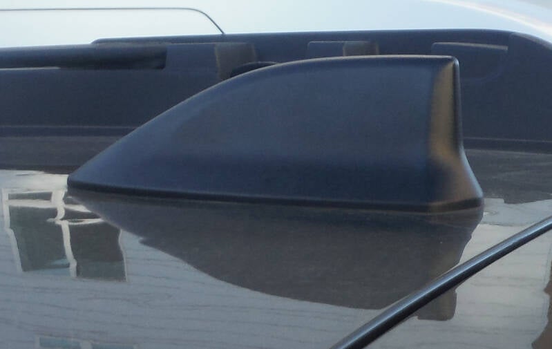
Newer, cooler looking and shorter, this baby is called a "sharkfin" antenna.
These are very inefficient, requiring an even higher gain amplifier to make up for it.
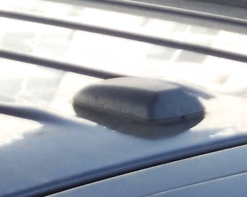
This antenna is on a late model car. It's about the size of a remote control.
Once again it is very inefficient and has a high gain amplifier inside.
This antenna is ok in the city, but if you like listening to AM radio on long trips,
far from the big city stations, disappointing on road trips, especially at night.

This is the AM/FM antenna on my car, a Subaru Forester.
It's printed on the inside of the left rear window.
Tough pic to take. Look for the thin lines.
They are the same conductive paint as used in rear window defrosters.
This is a very rarely seen antenna design.
It does use an amplifier.
Works way better than one would expect.

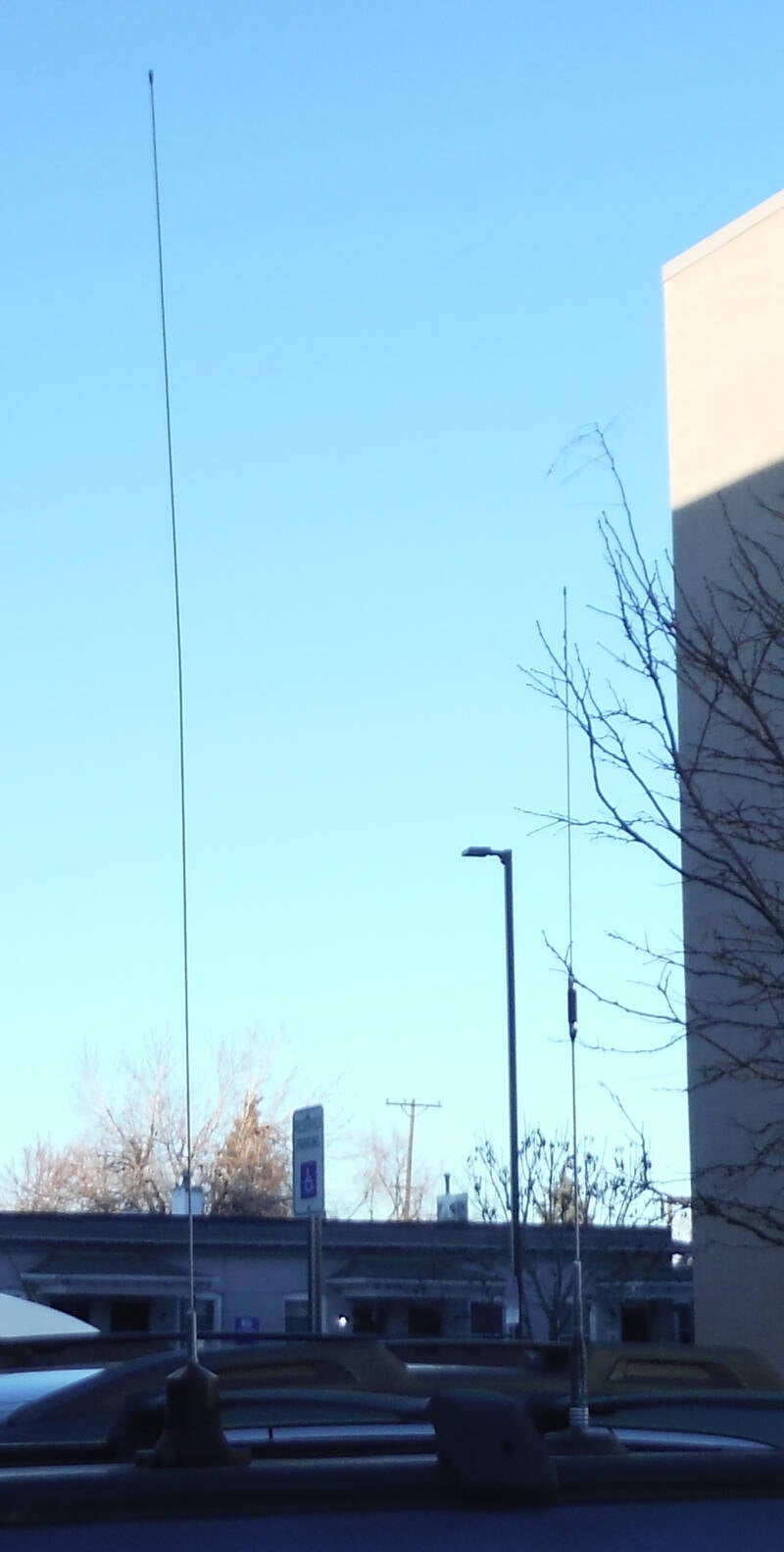
These 2 antennas are on top of my car.
The longer one is used for the 10/11/12 Meter HAM bands (24-30 MHz).
It is a Wilson 1000 CB antenna.
I cut off about 6" to make it resonant on the 10 meter HAM band.
The shorter one is a 3 band, resonant on the 144, 220 and 440 HAM bands.
It is a Nagoya TB-320A. I didn't have to cut it as it was tuned correctly from the factory.
They are both resonant antennas and similar antennas are tuned by adjusting the length.
The metal car roof below serves as the ground plane.
These 2 antennas perform way better than my indoor ones.
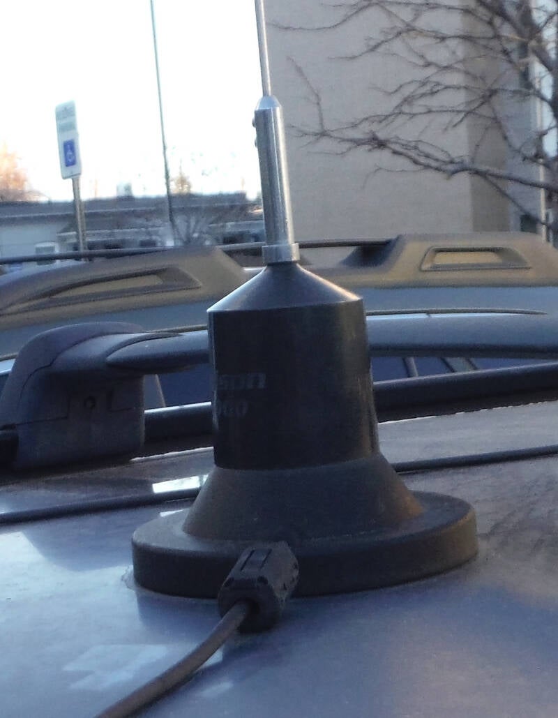
This is the magnetic base of the Wilson 1000 long antenna.
Inside is a coil of wire, called a base load that matches the impedance to 50 Ohms,
keeping the transmitter happy.
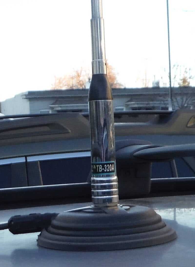
This is the magnetic base of the shorter Nagoya 3 band antenna.
It connects to a handheld radio laying on the passenger seat.
These 2 websites have a wealth of antenna info:
https://www.antennaexperts.co/blog/different-types-of-antennas-characteristics-of-antenna