PROJECTS
Here are some pictures of recent projects.
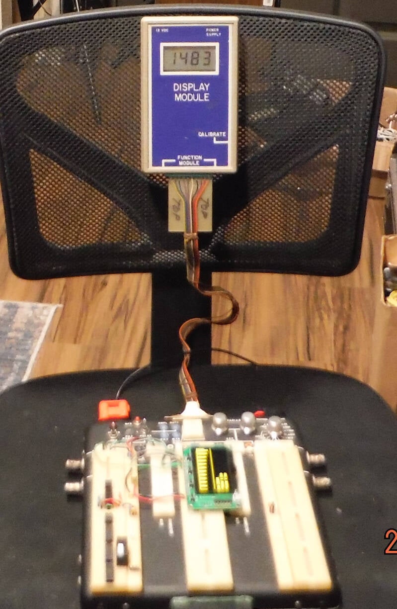
It is set up on a chair.
Powered from 12 VDC (the red plug).
Upper left and right are 4 BNC connectors that make it easy to connect external instruments to an experimental circuit.
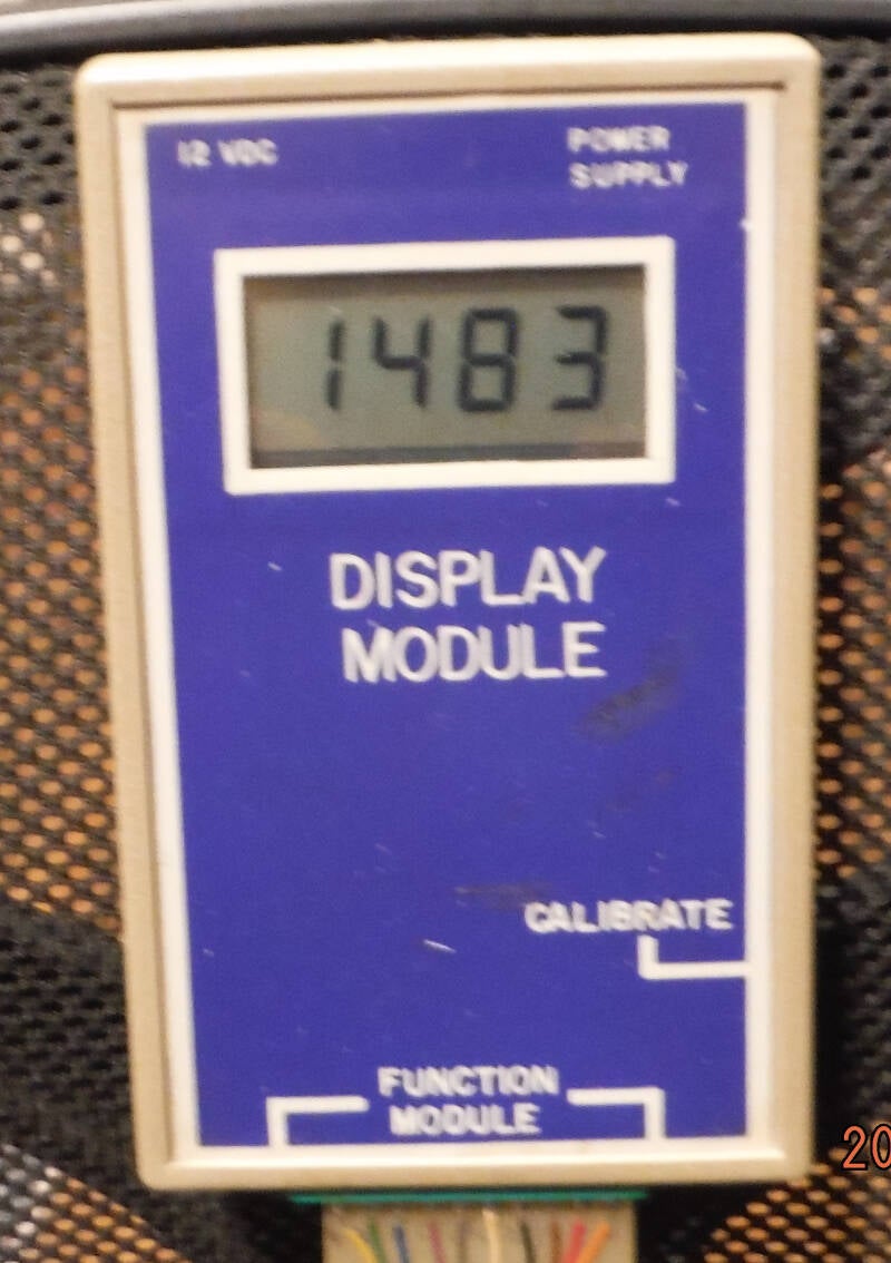
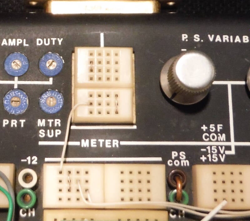
The Display Module is a digital readout of the power supplies voltage or current from the rotary switch.
It is reading the +15 Volt fixed supply which comes from the DC to DC converters.
See last pic.
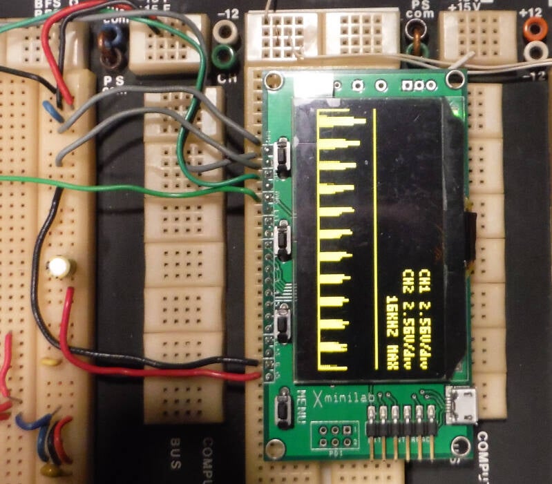
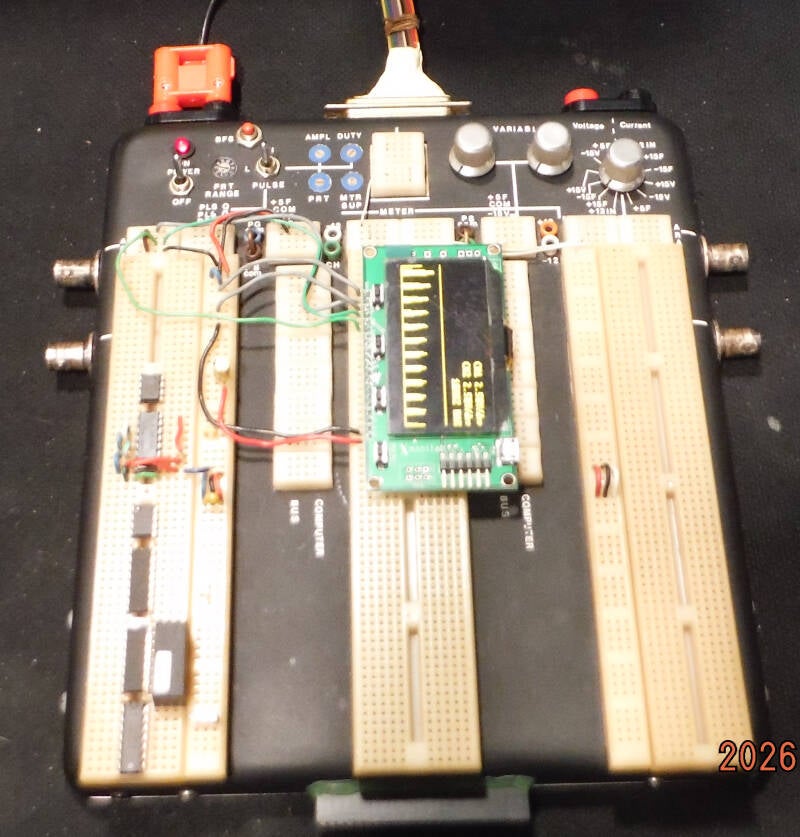
This is a Gabotronics X-Minilab that combines an oscilloscope, FFT (shown), waveform generator and logic analyzer.
It has become a part of the breadboard.
The guy who designed this is a genius. He figured out how to do this with a microprocessor, using just the on chip memory.
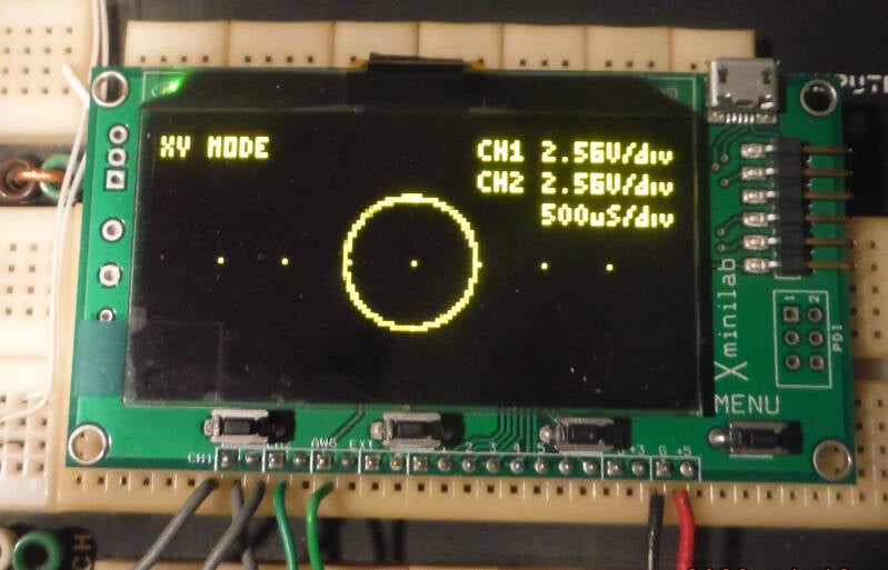
This pic shows the X-Minilab in X-Y mode.
The 1 kHz signal is 2 sine waves 90 degrees apart.
With a 5 Hz frequency, you can see it chasing it's tail, going round and round.
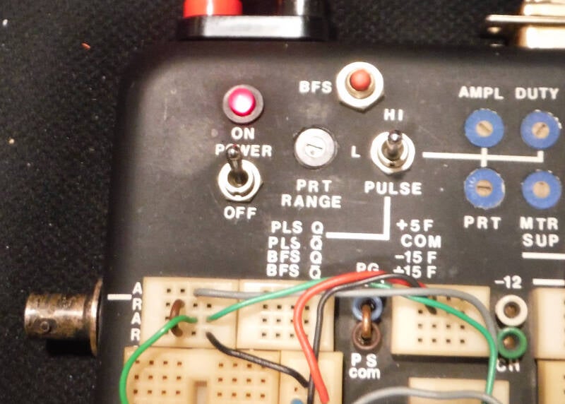
The small blue pots adjust the square wave, pulse generator.
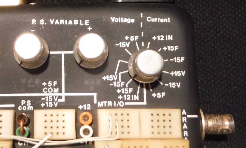
The rotary switch selects the voltage or current sent to the Display Module.
The 2 knobs are pots that adjust the variable power supplies.
The above pics are my "breadboard."
It allows an experimental circuit to be built without any soldering.
Most project circuits don't work on the first or second try.
It's easy to make changes until the circuit works correctly.
Then it can be assembled in an enclosure using a soldering iron.
The display module connects to the breadboard.
It uses the rotary switch in the upper right to read out the various voltages and currents
of the built in power supplies.
I built this baby way back in the 1980s.
Still use it very often today.
There is nothing like it even remotely available commercially.
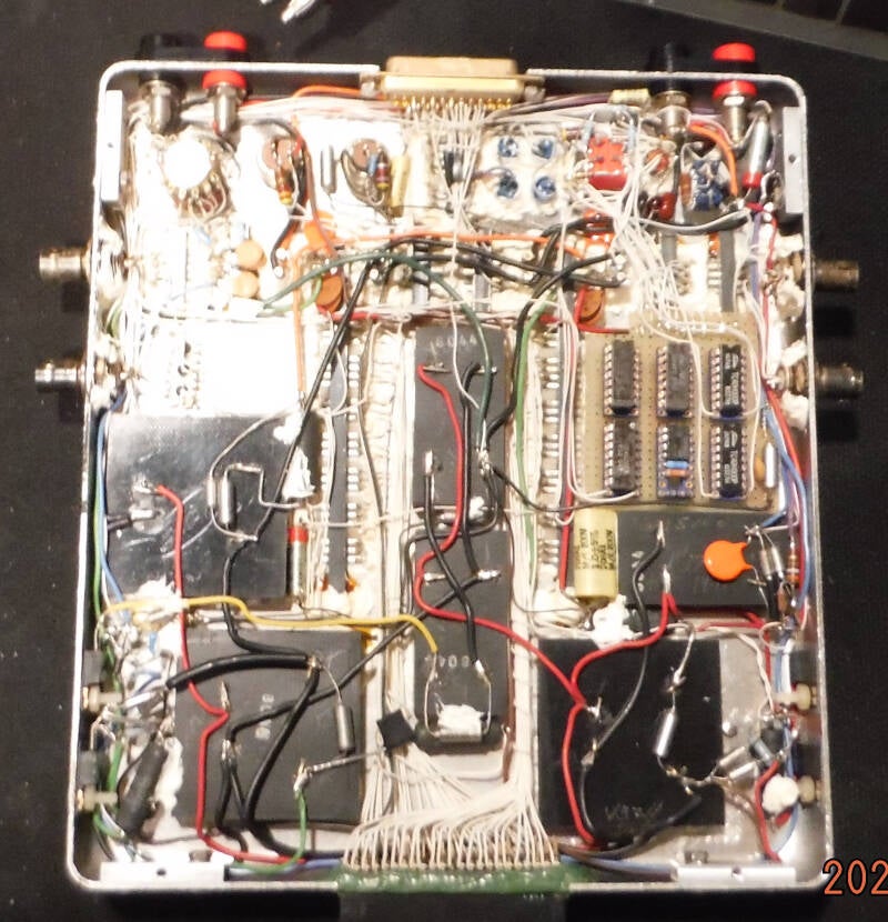
The last pic shows it's insides.
The black things are DC to DC converters that are the power supplies.
I look at this now and wonder how I managed to design and build it.
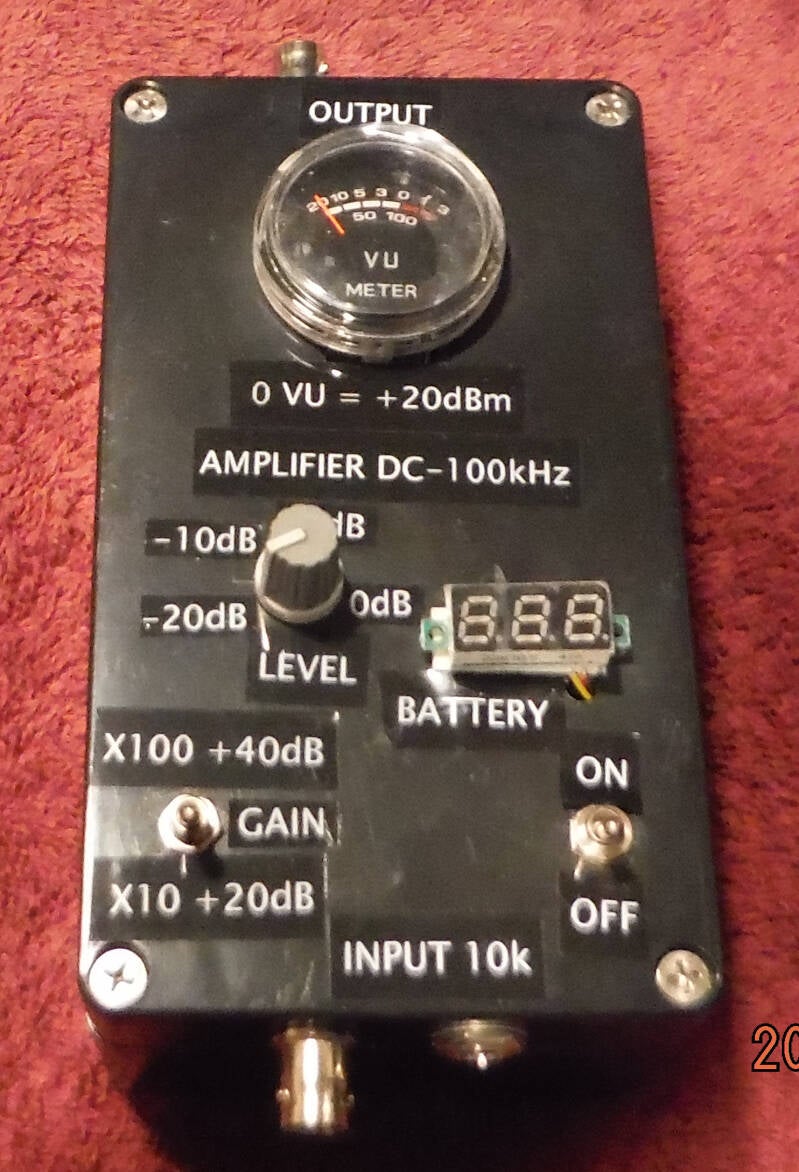
This project is an amplifier that can boost very small signals to as high as 30 Volts P-P.
It's bandwidth is DC to 100 kHz.
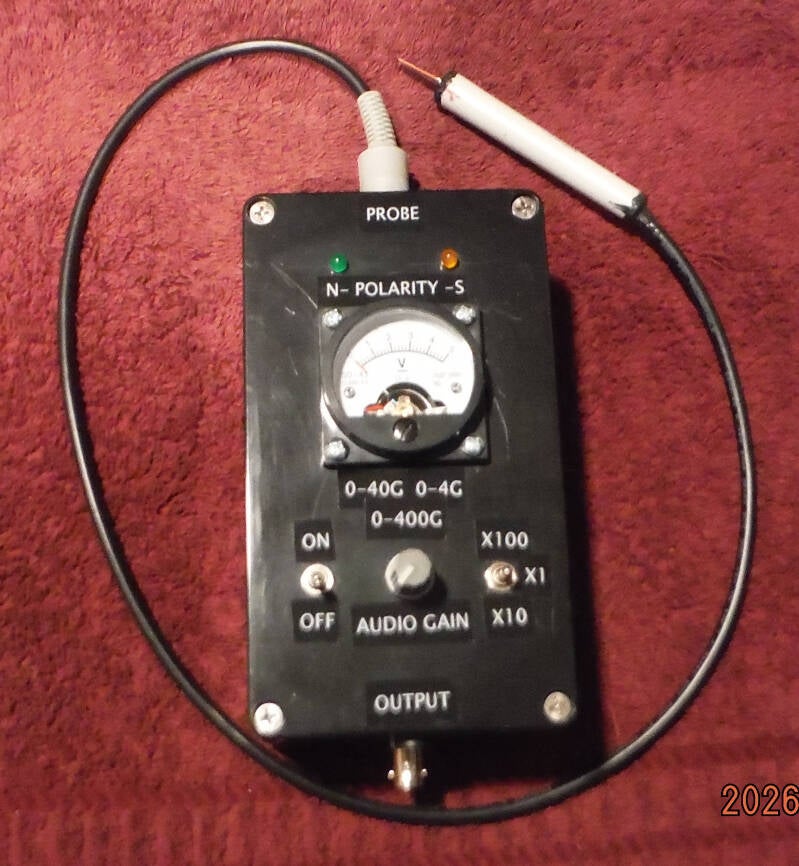
This project is a magnetic field meter.
It was a very challenging instrument to design and build.
The entire circuit was set up on the breadboard and had many changes until it worked correctly.
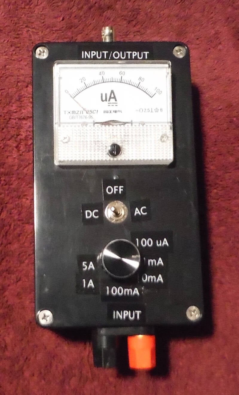
This project is a simple analog meter that measures DC or AC current.
It can read tiny current like 10 uA, up to 5 Amps full scale.